How to Test a Capacitor using Digital and Analog Multimeter – 8 Methods
8 Ways to Check and Test a Capacitor with a DMM and AMM (AVO)
In most electrical and electronics troubleshooting and repairing works, we face a common problem with capacitors where we want to know how to test and check a capacitor? Is it good, bad (dead), short or open?
Here, we can check a capacitor with analog (AVO meter i.e. Ampere, Voltage, Ohm meter) as well as digital multimeter either the capacitor is in good condition or should we replace it with a brand new one.
Note: To find the value of Capacitance, you need an analog or digital multimeter with capacitance measuring features.
Below are eight (8) methods to check & test that a Capacitor is Good, Defective, Open, Dead, or Short.
Related Posts:
- How to Test a Diode using Digital & Analog Multimeter – 4 Ways.
- How to Test a Relay? Checking SSR & Coil Relays
- How to Measure Capacitance using Multimeter
Method 1.
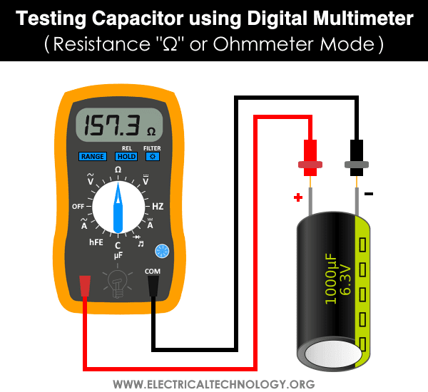
Test a Capacitor using Digital Multimeter – Resistance Mode
To test a capacitor by DMM (Digital Multimeter) in the Resistance “Ω” or Ohm mode, follow the steps given below.
- Make sure the capacitor is fully discharged.
- Set the meter on the Ohmic range (Set it at least on 1000 Ohm = 1kΩ).
- Connect the multimeter probes to the capacitor terminals (Negative to Negative and Positive to Positive).
- Digital multimeter will show some numbers for a second. Note the reading.
- And then immediately it will return to the OL (Open Line) or infinity “∞”. Every attempt of Step 2 will show the same result as shown in steps 4 and 5. It means that Capacitor is in Good Condition.
- If there is no Change, then Capacitor is dead.
Related Posts:
- Testing Electrical and Electronics Components and Devices with Multimeter
- How to Check a Transistor by Multimeter (DMM+AVO) – NPN & PNP – 4 Ways
Method 2.
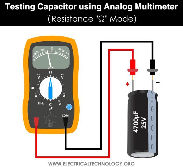
Check a Capacitor using Analog Multimeter – Ohm Mode
To check a capacitor by AVO (Ampere, Volt, Ohm Meter ) in the Resistance “Ω” or Ohm mode, follow the following steps.
- Make sure the suspected capacitor is fully discharged.
- Take an AVO meter.
- Rotate the knob on the analog meter to select the resistance “OHM” mode (Always, select the higher range of Ohms).
- Connect the Meter leads to the capacitor terminals. (COM to the “-Ve” and Positive to the “+Ve) terminals).
- Note the reading and compare with the following results.
- Short Capacitors: Shorted Capacitor will show very low resistance.
- Open Capacitors: An Open Capacitor will not show any movement (Deflection) on the OHM meter scale.
- Good Capacitors: Initially, it will show low resistance, and then gradually increases toward the infinite. It means that the capacitor is in good condition.
Method 3.
Checking Capacitor using Multimeter in the Capacitance Mode
Note: Testing a capacitor in the capacitance mode can only be performed if the analog or digital multimeter has the farad “Farad” of Capacitance “C” features. The function of capacitance mode in a multimeter can also be used to test the tiny capacitors. To do this, rotate the knob of the multimeter to the capacitance mode and follow the following basic instructions.
- Make sure the capacitor is fully discharged.
- Remove the capacitors from the circuit board.
- Now Select Capacitance “C” on the multimeter.
- Now connect the capacitor terminal to the multimeter leads.(Red to Positive and Black to Negative).
- If the reading is near to the actual value of the capacitor (i.e. the printed value on the Capacitor container box).
- Then the capacitor is in good condition. (Note that the reading may be less than the actual value of the capacitor (the rated value of capacitor due to the tolerance in ±10 or ±20 ).
- If you read a significantly lower capacitance or none at all, then the capacitor is dead and you should change it with a new one for proper operation.

Related Posts:
- How to Find the value of Ceramic Capacitors?
- How to Calculate the Suitable Capacitor Size in µ-Farads & kVAR for P.F Improvement
- How to Convert Capacitor μ-Farads to kVAR and Vice Versa? – For P.F Correction
Method 4.
Testing a Capacitor By Simple Voltmeter
To apply this method on polar and nonpolar capacitors, you must know the value of nominal voltage of capacitors. The level of voltage is already printed on the nameplate of electrolytic capacitors. While there are specific codes printed on ceramic and SMD capacitors. You may follow this guide which shows how to read and find the value of ceramic and non-polarized capacitors with related codes printed on it.
Also, you can use the DC Voltage “V” or Volt Mode in the digital or analog multimeter to perform this test.
- Make sure to disconnect a single lead (no worries if Positive (long) or negative (short)) of the capacitor from circuit (You may fully disconnect as well if needed)
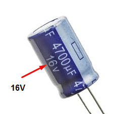
- Check the capacitor voltage rating printed on it (As shown in our below example where the voltage = 16V)
- Now charge this capacitor for a few second to the rated (not to the exact value but less than that i.e. charge a 16V capacitor with 9V battery. If the value of battery voltage is greater than the nominal voltage of the capacitor, it will damage or burst the capacitor.) voltage. Make sure to connect the positive (red) lead of the voltage source to the positive lead (long) of the capacitor and negative to negative. If you are not sure or unable to find the proper leads, here is the tutorial on how to find the negative and positive terminal of a capacitor.
- Set the value of voltmeter to the DC voltage and connect the Capacitor to the voltmeter by connecting the positive wire of the battery to the positive lead of the capacitor and negative to negative. You can use a digital or analog multimeter while selecting the DC voltage range for the same purpose.
- Note the initial voltage reading in the voltmeter. If it is close to the supplied voltage you gave to the capacitor, the Capacitor in in Good condition. If it shows far less reading, Capacitor is dead then. note that the voltmeter will show the reading for a very short time as the capacitor will discharge its stored volts in the voltmeter.

Note: The value of capacitor voltage should be less than the battery voltage. Otherwise, it will blast or burn the capacitor.
Related Posts:
- How to find The value of Burnt Resistor (By three handy Methods)
- How to Find the value of SMD Resistors
- How to calculate the value of resistors for LED’s
Method 5.
Test the Capacitor by Measuring the Value of Time Constant
We can find the value of a capacitor by measuring the Time Constant (TC or τ = Tau) if the value of capacitance of a capacitor is known in microfarad (symbolized µF) printed on it i.e. the capacitor is not blown and burnt at all.
In brief, the time taken by a capacitor to charge about 63.2% of the applied voltage when charges through a known value of resistor is called Time Constant of Capacitor (τ = Tau also known as RC time constant) and can be calculated via:
τ = R x C
Where:
- R = Value of known Resistor in Ohms
- C = Value of Capacitance
- τ = Tau (Time Constant)
For instance, if the supply voltage is 9V, then 63.2% of the supply voltage is around 5.7V. We will use a stopwatch and charge the capacitor until the value reaches 5.7V. Stop the watch and note the reading of time in seconds. For more details, check the example given below the instructions.
Now, let’s see how to find the value of a capacitor by measuring the Time Constant. (Note: An oscilloscope will do this better with precise value instead of multimeter.
- Make sure to disconnect as well as discharge the capacitor from the board.
- Connect a known value of resistance (e.g. 5-10kΩ Resistor) in series with the capacitor.
- Apply the known value of supply voltage. (e.g. 12V or 9V) to the capacitor connected in series with a 10kΩ resistor.
- Now, measure the time taken for the capacitor to charge about 63.2% of the applied voltage. For instance, if the supply voltage is 9V, then 63.2% of this is around 5.7V.
- From the value of the given resistor and measured time via a stopwatch, calculate the value of capacitance by Time Constant formula i.e. τ = Tau (Time Constant).
- Now compare the calculated value of capacitance with the value of capacitor printed to it.
- If they are the same or nearly equal with , The capacitor is in good condition. If you find a noticeable difference in both values, time to change the capacitor as it is not functioning well.

Example: Suppose, we are going to test a 16V, 470μF capacitor. If the supply voltage is 9V, then 5.7V is 63.2% of the supply voltage. We will connect the capacitor to the battery for charging and start the stopwatch. When the meter shows a 5.7V, we will stop the stopwatch. Suppose, the stopwatch shows 4.7 seconds of time duration.
Now, use the time constant τ = RC formula for measuring the capacitance i.e. C = τ / R
C = 4.7 seconds / 10kΩ
C = 0.47mF = 470μF
Now compare the calculated value of the capacitance with the value of the capacitor printed on it.
- If the calculated value is nearly equal or having a difference of ±10 to ±20 to the desired capacitor. It is a Good Capacitor.
- If the calculated value is far away with a noticeable difference, the capacitor is faulty.
- In our example, the calculated value is almost the same as the actual value of the capacitor. It means the capacitor is in good condition.
The discharge time can also be calculated. In this case, the time taken by the capacitor to discharge to 36.8% of the peak voltage can be measured.
Good to know: The time taken by a capacitor to discharge about 36.8% of the peak value of the applied voltage can be also measured. The discharge time can be used as the same in the formula to find the value of the capacitor.
Method 6.
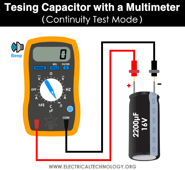
Test the Capacitor by Continuity Test Mode
In the DMM and AVO meter, the continuity test mode can also be used whether the capacitor is good, open or short. To do so, follow the simple instructions below.
- Disconnect the power supply and remove the capacitor from the circuit board.
- Fully discharge the capacitor using a resistor.
- Rotate the knob and set the multimeter in continuity test mode.
- Make a contact of the positive (RED) probe of the multimeter to the Anode (+) and Common (Black) probe to the Cathode (-) terminal of the capacitor.
- If the multimeter shows a sign of proper continuity (beep sound or LED light) and suddenly stops and shows an OL (open line). It means the capacitor is in good condition.
- If the multimeter doesn’t show a continuity sign with beep or led, it means the capacitor is open.
- If the multimeter LED lights ON and makes a continuous beep sound, it means the capacitor is short and it should be replaced with a new one.
Method 7.
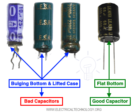
Test the Capacitor by Visual & Apparent Checking
It is the basic approach to determine the defective capacitor without a multimeter by observing the apparent signs appearing on it.
The capacitor is failed and damaged if you find any of the following conditions.
Bulging Top Vent of Capacitor
The top vent of the electrolytic capacitor in shape of K, T or X are the weak points made to release the pressure during the failure of a capacitor to avoid serious damage to the surrounding and any other components connected near to it.
If you find a bulging top of the capacitor, it is the electrolytic discharge (black, white, orange color which depends on the electrolytic material) i.e. the capacitor releases a gas pressure during failure and breaker the top vent of the capacitor.

Bulging Bottom and Lifted Case of Capacitor
If the produced gas pressure does not break the top vent of the capacitor during failure, it goes through the bottom and pushes the rubber which makes the bottom bulge and lifts the case.
Testing SMD and Ceramic Capacitors
If you find the following signs on ceramic or tiny SMD capacitors, they are faulty and need to be changed with the correct ones.
Broken or cracks in the casing.
Damaged or any sign of burnt casing.
A hole in the casing.
Broken terminals.

Related Posts:
How to Test & Fix the Printed Circuit Board (PCB) Defects?
How to Test for Continuity in Electrical Components with Multimeter?
How to Test a Battery with Test meter?
Method 8.
Traditional Method to Test & Check a Capacitor
Note: Not Recommended for everyone but professionals only. Please be careful to do this practice as it is dangerous. Make sure that you are a professional electrical engineer / electrician and you really know that you are doing something hazardous.
Please follow the safety precautions and warnings before applying this method. This is only applicable in an emergency (where replacing the capacitor with a proper value is important) and there are no other options to check the damaged capacitor. because serious damages may occur during this practice).
If you are not sure, (because serious damages may occur during this practice) follow the other options (1 – 7) as alternative methods to troubleshoot the capacitor.
Suppose you want to check the Capacitor (for example, fan capacitors, room air cooler capacitors or tinny capacitors in a circuit board / PCB etc.)
Warning & Safety Precautions for Testing a Capacitor by Method# 8.
For proper safety, use a 12 to 24V DC source in case of both polar and non polar capacitors with a 1kΩ~10kΩ, 5~50W resistor. The resistor should be connected in series with battery and capacitor positive terminals. This way, it will reduce the excessive current while charging the capacitor.
In case of absence of DC source (like batteries), the high rated capacitors (i.e. fan capacitors rated for. 3.5µF, 120, 230 or 400V) you may use 120-230V AC, but you have to connect a series of resistors (say 1kΩ~10kΩ, 5~50Watts) to connect between capacitor and 230V AC supply. This way, it will reduce the charging and discharging current. Here is the step by step tutorial on how you may check a capacitor by this method.

Comments